- 您现在的位置:买卖IC网 > Sheet目录1992 > CY28317PVXC-2 (Silicon Laboratories Inc)IC CLK FTG VIA PL/E133T 48SSOP
CY28317-2
....................... Document #: 38-07094 Rev. *B Page 8 of 20
Bit 5
WD_TIMER4
1
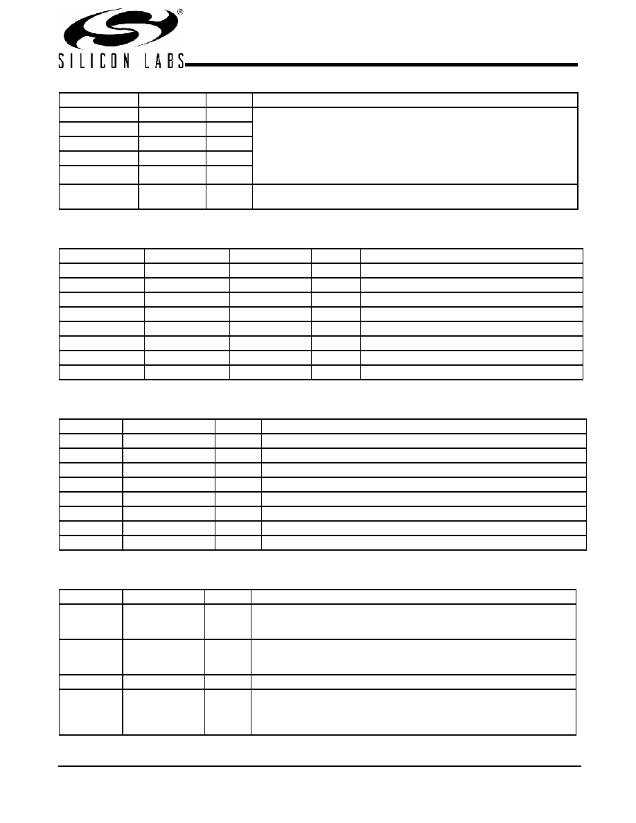
These bits store the time-out value of the Watchdog Timer. The scale of the
timer is determined by the prescaler.
The timer can support a value of 150 ms to 4.8 sec when the prescaler is set
to 150 ms. If the prescaler is set to 2.5 sec, it can support a value from 2.5 sec
to 80 sec.
When the Watchdog Timer reaches “0,” it will set the WD_TO_STATUS bit and
generate Reset if RST_EN_WD is enabled.
Bit 4
WD_TIMER3
1
Bit 3
WD_TIMER2
1
Bit 2
WD_TIMER1
1
Bit 1
WD_TIMER0
1
Bit 0
WD_PRE_SC
ALER
0
0 = 150 ms
1 = 2.5 sec
Byte 6: Watchdog Timer Register (continued)
Bit
Name
Default
Pin Description
Byte 7: Control Register 7
Bit
Pin#
Name
Default
Pin Description
Bit 7
–
Reserved
0
Reserved
Bit 6
25
24_48MHz_DRV
1
0 = Norm, 1 = High Drive
Bit 5
26
48MHz_DRV
1
0 = Norm, 1 = High Drive
Bit 4
–
Reserved
0
Reserved
Bit 3
–
Reserved
0
Reserved
Bit 2
–
Reserved
0
Reserved
Bit 1
–
Reserved
0
Reserved
Bit 0
–
Reserved
0
Reserved
Byte 8: Vendor ID and Revision ID Register (Read Only)
Bit
Name
Default
Pin Description
Bit 7
Revision_ID3
0
Revision ID bit[3]
Bit 6
Revision_ID2
0
Revision ID bit[2]
Bit 5
Revision_ID1
0
Revision ID bit[1]
Bit 4
Revision_ID0
0
Revision ID bit[0]
Bit 3
Vendor_ID3
1
Bit[3] of Cypress Semiconductor’s Vendor ID. This bit is read-only.
Bit 2
Vendor_ID2
0
Bit[2] of Cypress Semiconductor’s Vendor ID. This bit is read-only.
Bit 1
Vendor _ID1
0
Bit[1] of Cypress Semiconductor’s Vendor ID. This bit is read-only.
Bit 0
Vendor _ID0
0
Bit[0] of Cypress Semiconductor’s Vendor ID. This bit is read-only.
Byte 9: System RESET and Watchdog Timer Register
Bit
Name
Default
Pin Description
Bit 7
SDRAM_DRV
0
SDRAM clock output drive strength
0 = Normal
1 = High Drive
Bit 6
PCI_DRV
0
PCI clock output drive strength
0 = Normal
1 = High Drive
Bit 5
Reserved
0
Reserved
Bit 4
RST_EN_WD
0
This bit will enable the generation of a Reset pulse when a Watchdog Timer
time-out occurs.
0 = Disabled
1 = Enabled
发布紧急采购,3分钟左右您将得到回复。
相关PDF资料
CY28323OXC
IC CLOCK BROOKDALE GPENT4 48SSOP
CY28354OXC-400
IC BUFF 273MHZ 4DDR DIMM 48SSOP
CY28378OXC
IC CLOCK CK408/TITAN 845 48SSOP
CY284108ZXC
IC CLOCK SERV CK410B 56TSSOP
CY28410OXC-2
IC CLOCK CK410 GRANTSDALE 56SSOP
CY28410OXC
IC CLOCK CK410 GRANTSDALE 56SSOP
CY28411ZXC
IC CLOCK CK410M ALVISO 56TSSOP
CY28442ZXC-2
IC CLOCK ALVISO PENTM 56TSSOP
相关代理商/技术参数
CY28317PVXC-2T
功能描述:时钟发生器及支持产品 NB Clk VIA SDRAM Chipsets / Tualatin RoHS:否 制造商:Silicon Labs 类型:Clock Generators 最大输入频率:14.318 MHz 最大输出频率:166 MHz 输出端数量:16 占空比 - 最大:55 % 工作电源电压:3.3 V 工作电源电流:1 mA 最大工作温度:+ 85 C 安装风格:SMD/SMT 封装 / 箱体:QFN-56
CY28317ZC-2
制造商:CYPRESS 制造商全称:Cypress Semiconductor 功能描述:FTG for Mobile VIA PL133T and PLE133T Chipsets
CY28317ZC-2T
制造商:CYPRESS 制造商全称:Cypress Semiconductor 功能描述:FTG for Mobile VIA PL133T and PLE133T Chipsets
CY28322
制造商:未知厂家 制造商全称:未知厂家 功能描述:Clocks and Buffers
CY28322-2
制造商:CYPRESS 制造商全称:Cypress Semiconductor 功能描述:133-MHz Spread Spectrum Clock Synthesizer with Differential CPU Outputs
CY28322ZC-2
制造商:Rochester Electronics LLC 功能描述:- Bulk
CY28322ZC-2T
制造商:Rochester Electronics LLC 功能描述:- Bulk
CY28323
制造商:CYPRESS 制造商全称:Cypress Semiconductor 功能描述:FTG for Intel㈢ Pentium㈢ 4 CPU and Chipsets